Vision LLM · Appearance QC / Field Practice
Automotive: Plastic Part Defect Inspection — Field Practice
On black, complex plastic parts, short shots, structural faults and edge burrs sit in different local views— coaxial light stabilises imaging, few-shot segmentation sees the defects, and events plus a state machine merge five checks into a traceable OK / NG.
Key takeaways
- Five checks, continuous IDs. Hook-tip short shot/break, bracket short shot/deform, top snap anomaly, and edge-burr height at two points; the scope is closed with no numbering gaps, and each of the five has a representative trial result.
- Coaxial light + shielding. On glossy black curves, coaxial illumination creates a stable bright/dark cue; ambient light is blocked so thresholds can hold.
- Few-shot segmentation. A new defect class can start with 1–10 sample images and minutes of setup; geometry thresholds live in the recipe—no full retrain to change a tolerance.
- Three stations, one tensor flow. Hook/bracket, top snap and edge burrs are acquired on separate views, then events feed one state machine keyed by part ID.
- Edge-local inference. Capture, segmentation, decision and archive run on the edge GPU; frames stay on site, and the same pattern scales across stations.
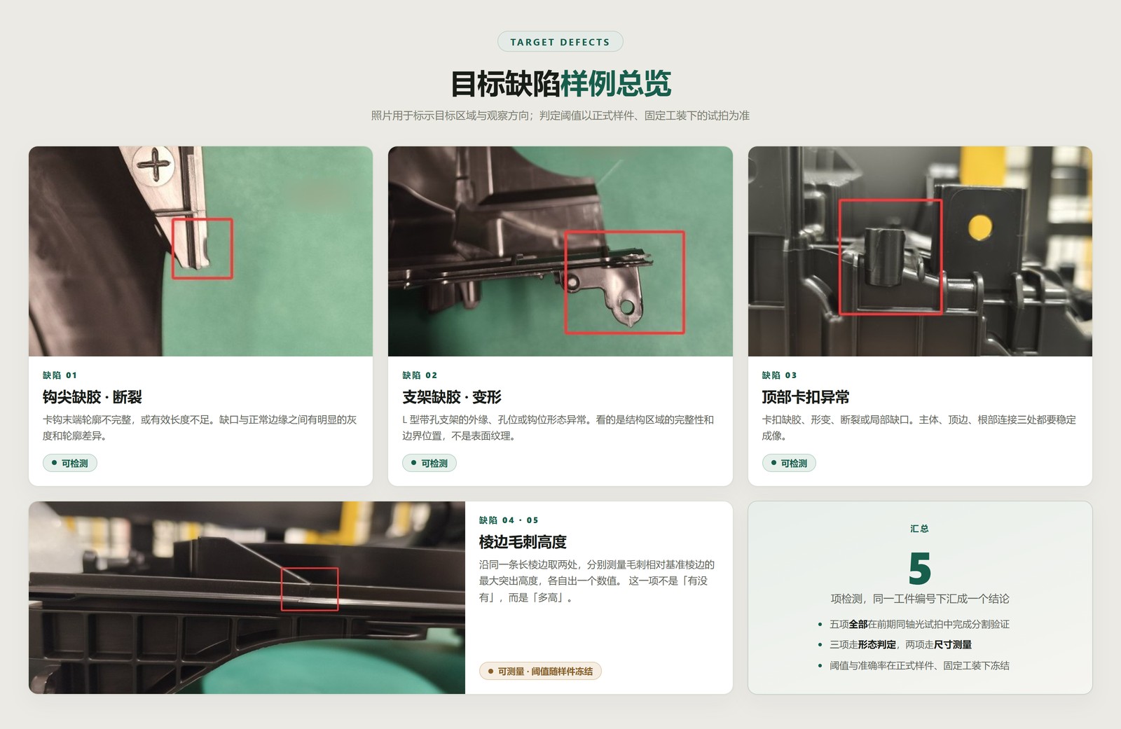
Manual inspection is hard to keep stable here: short shots, fine burrs and structural faults are scattered, and long observation is limited by fatigue, experience and cycle time. Early coaxial trials already showed clear contours and grey-level contrast—and pixel-level segmentation. This plan pushes “visible” to “decidable, reviewable and mergeable”.
01/9Challenge
The hard part is freezing imaging and criteria—not “having a model”
Ribs, holes and edges occlude each other; different defects need different viewing directions. When ambient light shifts, specular highlights move with it—the same notch looks bright one day and dark the next. A classic “collect thousands of images and train a dedicated appearance model” path breaks on mould changes, batch changes and surface changes: long onsite training, slow replication.
So the path changes: freeze optics and pose first, cover irregular short shots and burrs with Transformer few-shot segmentation, and attach area, length and protrusion height to configurable thresholds. Inference stays on the edge GPU—protecting both cycle time and data locality.
Make the defect look the same in the image first; only then talk about accuracy. Otherwise thresholds cannot freeze, and the model only tracks drifting highlights.
02/9Defects
Five checks: three morphology, two metrology
The inspection scope converges to the five items below, numbered without gaps. All five completed segmentation validation in the coaxial trial; thresholds and accuracy are frozen on official samples in a fixed fixture.
| ID | Defect | Method | Decision focus |
|---|---|---|---|
| 01 | Hook tip short shot / break | Seg. + contour / length | Incomplete tip contour or insufficient effective length |
| 02 | Bracket short shot / deform | Seg. + shape compare | Integrity of outer edge, holes and hook seat |
| 03 | Top snap anomaly | Seg. + structural integrity | Short shot, deformation, break or local notch |
| 04 | Edge burr height A | Seg. + baseline offset | Max protrusion vs. reference edge over threshold |
| 05 | Edge burr height B | Seg. + baseline offset | Second point on the same edge; separate value & decision |
Defect 02 is about structural integrity, not surface texture. Defects 04 / 05 ask “how tall”, not “is there a burr”—changing a tolerance only edits the millimetre threshold.
03/9Optics
Coaxial lighting: turn defects into a stable contrast cue
The part is black, curved and locally specular. Oblique light makes highlights drift with pose and ambient light. Coaxial lighting aligns illumination with the viewing axis: a good surface returns light to the lens (brighter); notches and burr sidewalls deflect light away (darker). A light shield then kills ambient light so the same defect looks the same across shifts.
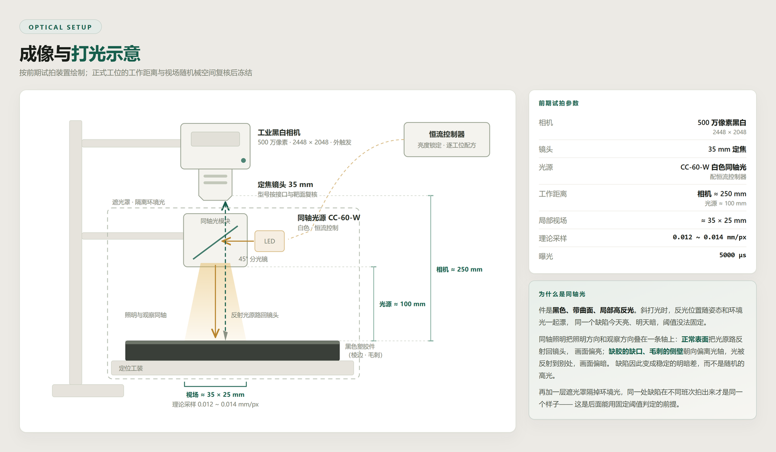
Camera, lens and coaxial light follow the trial selection; exposure, WD, station count and structure freeze after official samples, mechanical space and cycle time are checked. Light parameters are managed in recipes per station.
04/9Tensor Flow
Three station branches into one workflow
The vision agent runs on the edge: configuration, inference, HMI and outputs share one software stack. Zero-code canvas wiring—drag operators, connect data ports. This project is not a single serial chain: three station branches run in parallel (capture → preprocess → segmentation → event detection), then merge into a state machine, save images and talk to the PLC over serial.
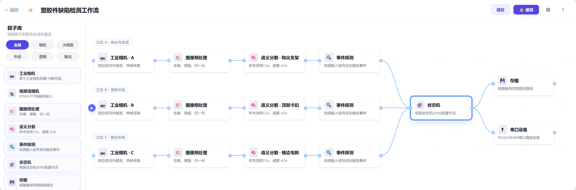
Double-click a node for the sub-editor: segmentation → annotate tool, event detection → GPU event composer, state machine → state-graph editor. A product change is mostly recipes and samples, not a rewrite.
05/9Segmentation
Pixel masks: lock a new defect with 1–10 samples
Short-shot boundaries are irregular and burr contours are fine; boxes fit poorly. The plan uses pixel-level semantic segmentation: each class is defined in the annotate tool from a small set of line images—product guidance is 1–10 sample images and minutes of setup. Masks then drive area, length or protrusion vs. a baseline. Training and inference stay on the local edge GPU; station frames do not leave the plant.
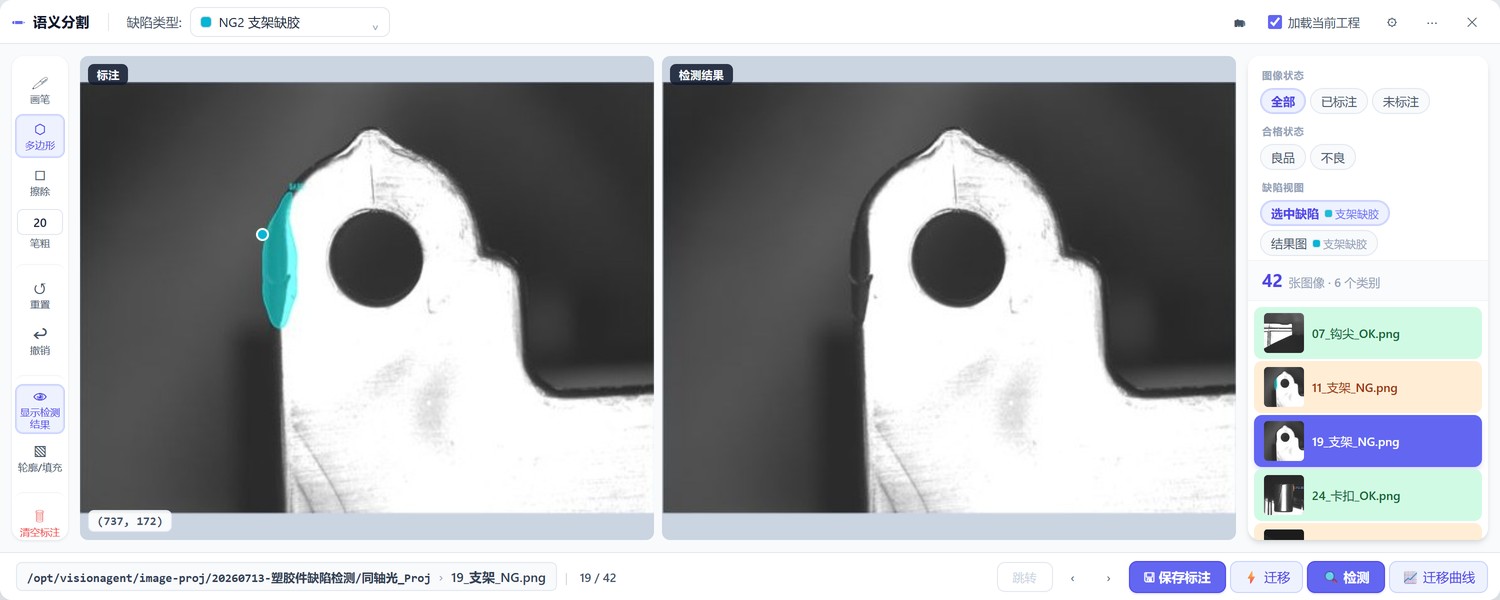
Across moulds and batches, similar morphologies often need only a few extra labels to transfer—the field value of a few-shot base versus “one long train per defect”: shorter launch, less permanent onsite training staff.
06/9Trial Evidence
All five items, each with its own detection result
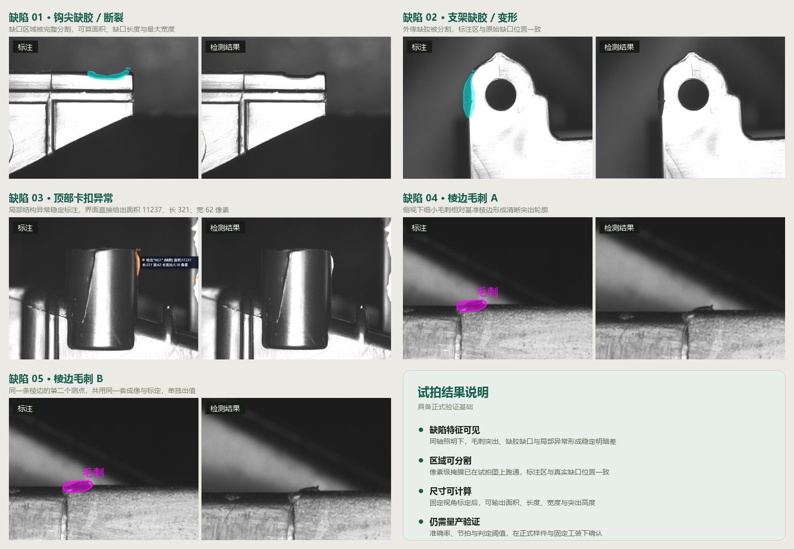
Whether the project is worth starting rests on one question: under coaxial light, do the target defects actually form learnable, segmentable features? That cannot be argued—it has to be shot. The trial went through all five items one by one; below is a representative detection result for each: human labels on the left, model output on the right.
| # | Feature | Measurement | Trial conclusion |
|---|---|---|---|
| 01 | Short shot or break forms a continuous contour gap, clearly different from a sound edge | Defect area, gap length, max width | Representative edge short shot segmented accurately |
| 02 | Short shot at the bracket edge shows clear area and contour change | Short-shot area, contour deviation, hole integrity | Labelled region matches the real gap position |
| 03 | Snap short shot, break or deformation changes region contour and area | Height, width, endpoints, deviation from template | UI reports area 11237, length 321, width 62 px |
| 04 | In side view, a fine burr forms a clear protrusion against the reference edge | Fit a baseline, take max perpendicular distance | Fine burr segmented accurately; ready for calibrated height |
| 05 | Second measuring point on the same edge; same feature and criterion as 04 | Same baseline, its own max perpendicular distance | Shares imaging and calibration; reports and judges separately |
These frames prove the route works—features are visible, locatable and segmentable. They do not prove accuracy is already met. Final accuracy, cycle time and thresholds still come from validation on production samples in fixed fixtures.
07/9Events
Turn masks into “hook short shot” and “burr over height”
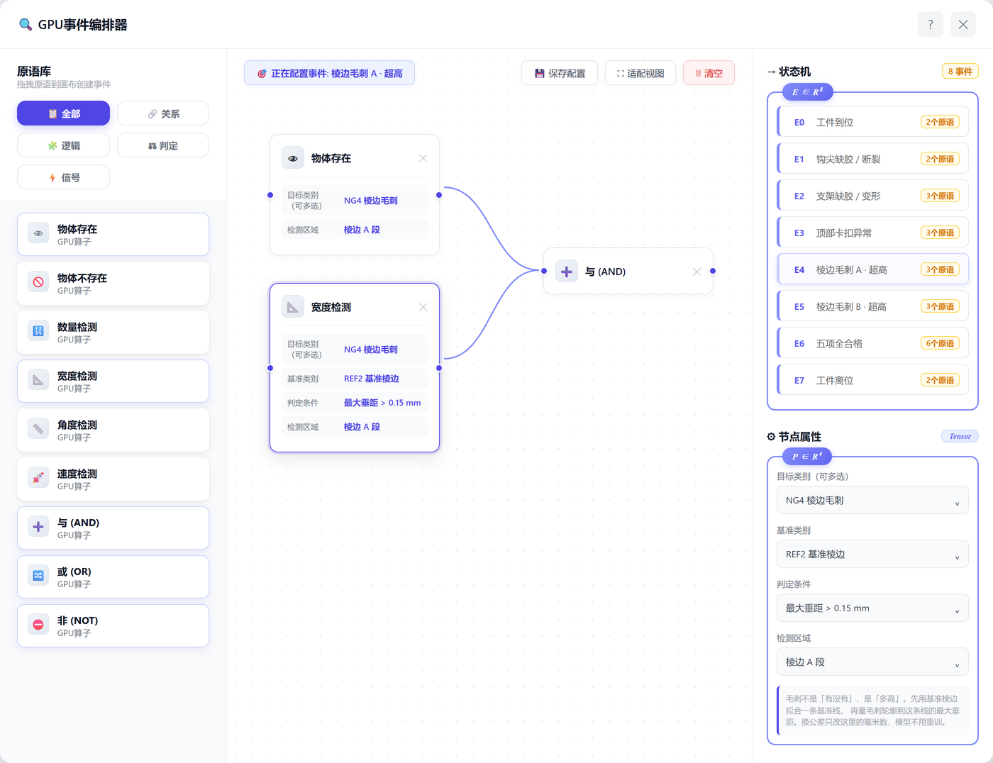
Segmentation sees pixels; the business needs decidable events. Events are listed for the state machine; logic is built in the GPU event composer: presence, width measurement and other primitives get a class and ROI, then AND / OR / NOT. Burrs use width measurement for max perpendicular distance—fit a clean reference edge, measure contour-to-baseline distance; the millimetre limit lives in the recipe.
08/9State Machine
Arrive, inspect, merge five results into one OK / NG
The state machine turns discrete events into a line flow: wait for part → item checks → pass or NG; NG parts leave for review and can return after rework. All five must pass to release and count; any hit saves NG images and alarms. Results join by part ID across stations so you never get “each station OK, whole part missed”.
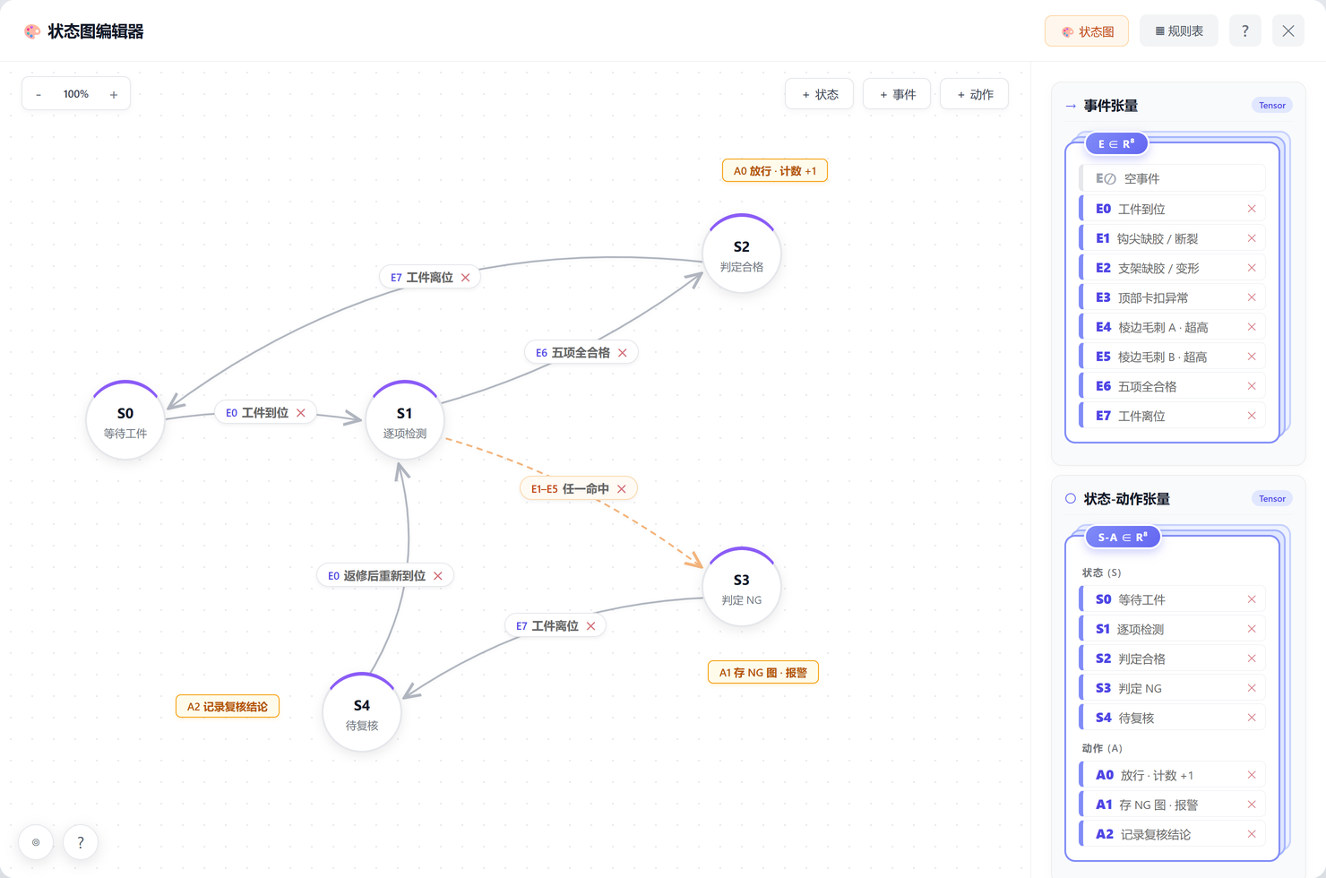
E6 (all five pass) releases on the upper branch; E1–E5 any hit goes NG; review conclusions archive for a rework/recheck loop.The machine does not answer “does this frame look like a defect?”—it answers “may this part pass under the current recipe?”, with evidence.
09Deployment
Independent views, one conclusion per part
Station count can merge with mechanical space; viewing directions stay independent:
- Station A · hook & bracket: fixed local views for defects 01 and 02 (short shot, break, structural integrity).
- Station B · top snap: fixed lighting and pose for defect 03 morphology.
- Station C · edge burr: side profile, baseline fit, heights for defects 04 and 05.
Fixtures limit pose drift; shields and light recipes are per station. The edge unit runs multi-station inference, HMI and archive; arrival I/O / PLC triggers capture and receives pass signals. The front end covers live view, NG alarm, manual review and search by time / part ID / defect; recipes manage cameras, model versions, thresholds and station enable—changeovers edit configuration, not a whole line software rewrite.
Equipment list
The table fixes categories and purpose only; exact models freeze after production samples, mechanical space and cycle time are reviewed.
| # | Item | Configuration | Purpose |
|---|---|---|---|
| 1 | Industrial mono camera | 5 MP, 2448 × 2048, external trigger | Capture defect images at each independent station |
| 2 | Fixed-focus lens | 35 mm in the trial; reviewed per station space | Cover ~35 × 25 mm local field with enough pixels on target |
| 3 | Coaxial light | CC-60-W white coaxial, constant-current driver | Boost short-shot and burr contrast per the trial path |
| 4 | Fixture / light shield | Repeatable location, quick clamp, serviceable | Fix part pose and block ambient light |
| 5 | Arrival sensor / PLC I/O | Industrial discrete I/O or fieldbus | Trigger capture, receive results, control pass-through |
| 6 | Edge compute unit | Sized for multi-station parallel inference and storage | Inference, dimensioning, UI and archive |
| 7 | HMI and alarm | Industrial display, tri-colour tower, buzzer | Onsite display, alarm, review and operation |
Delivery follows freeze requirements → station trials → mass-production samples → model & repeatability → onsite acceptance; hardware, lights, models and thresholds freeze only after validation. Fit: plastic appearance QC with frequent part/defect change and multi-view local checks. Deep cavities or burrs far off the imaging plane need process help or an orthogonal view.
Leo
PhD in computer vision · VisionAgent solutions & delivery
Focus: few-shot segmentation and industrial scene understanding. Move appearance QC from “one long train per defect” to “few-shot segmentation + event rules + state-machine merge”, so tolerances stay decoupled from perception.
Now working on edge-GPU inference, cross-domain transfer and closed-loop site data. This article records the optics choice, five-defect scope and platform configuration path for plastic-part inspection.