In industrial inspection, 80% of success or failure lies in the optics, not the algorithm. This document makes clear how to image black-part defects sharply: first separate which defects are feasible and which are currently not, then lock down the imaging principle, field of view, working distance, camera/lens and light source for each of the three feasible defects.
Overview & Core Principle
The inspected objects are black injection-molded parts, and the defects are mostly local, small-scale structural anomalies (missing material, fracture, deformation, flash), not large-area surface problems. The solution uses a single station + fixed angle + dedicated light source: each defect is lit by the method best matching its physical nature, imaged independently and never merged onto one station.
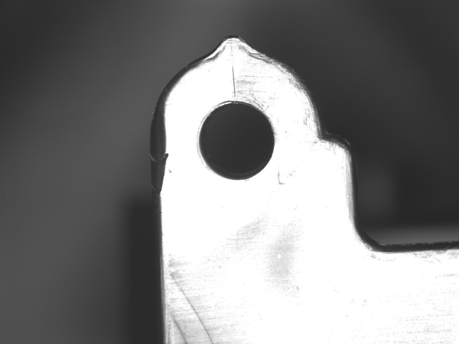
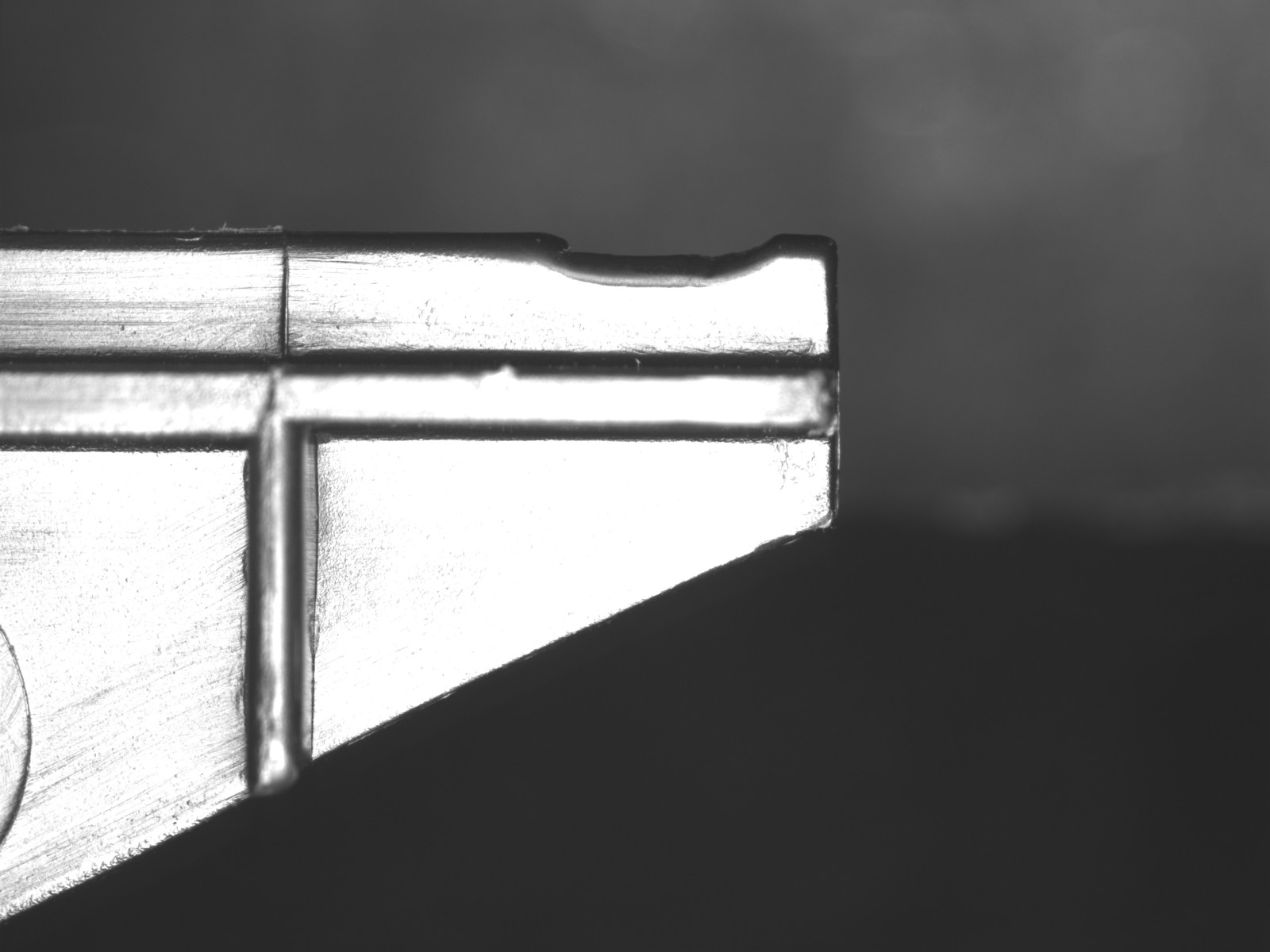
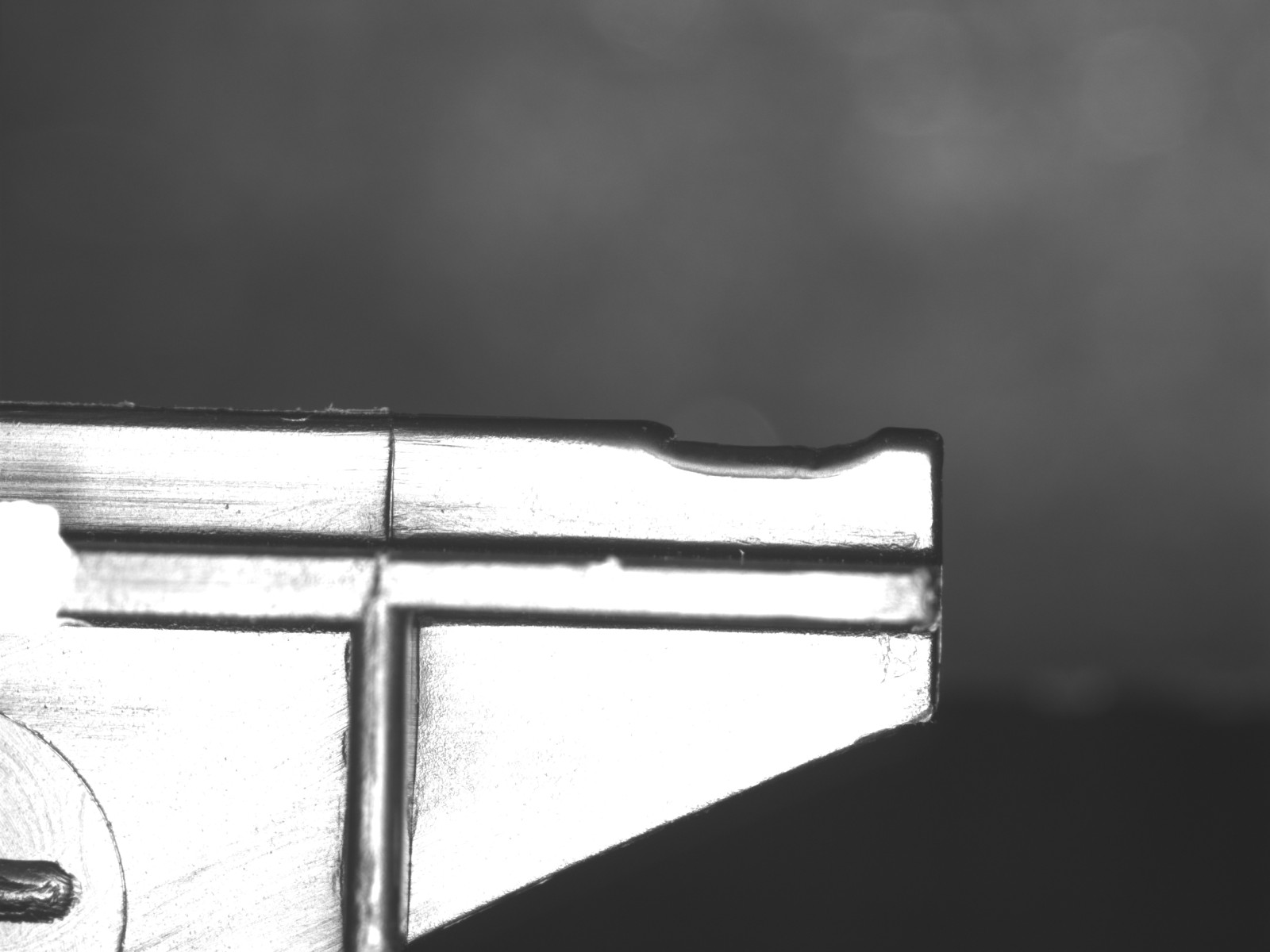
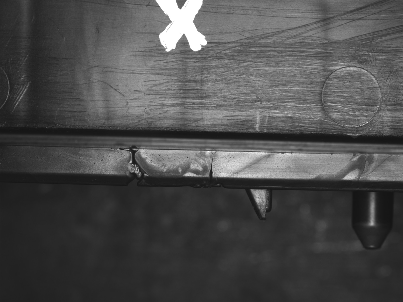
Four difficulties
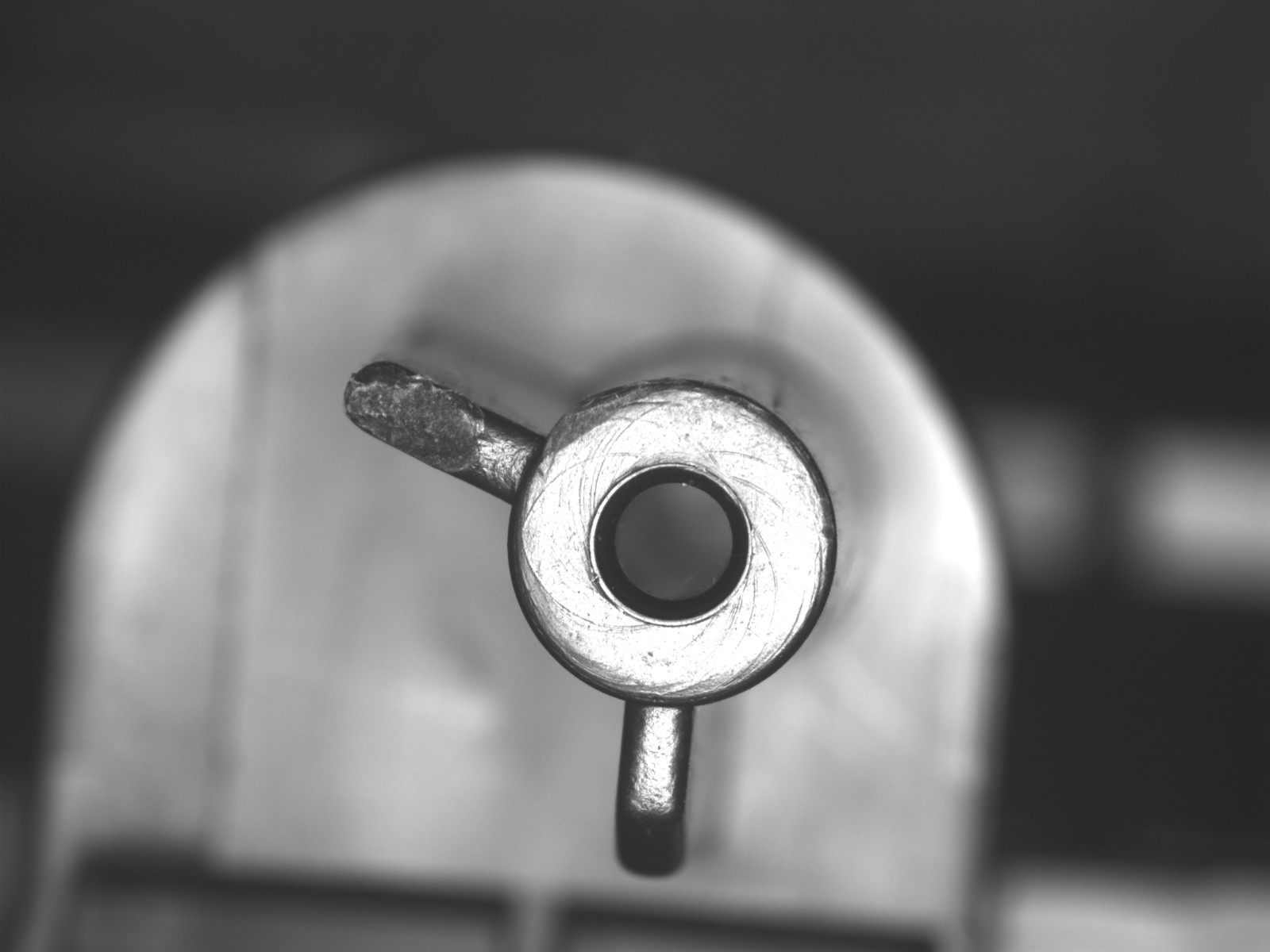
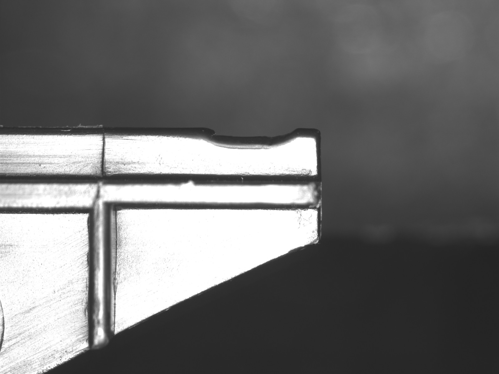
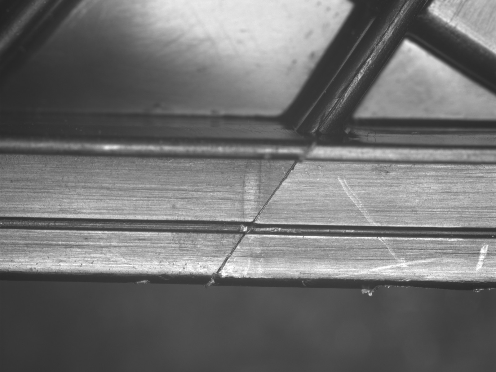
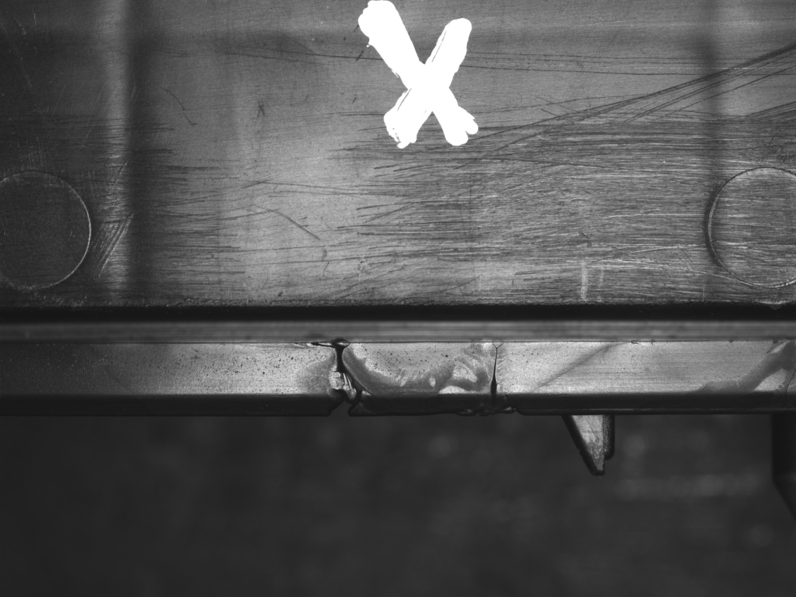
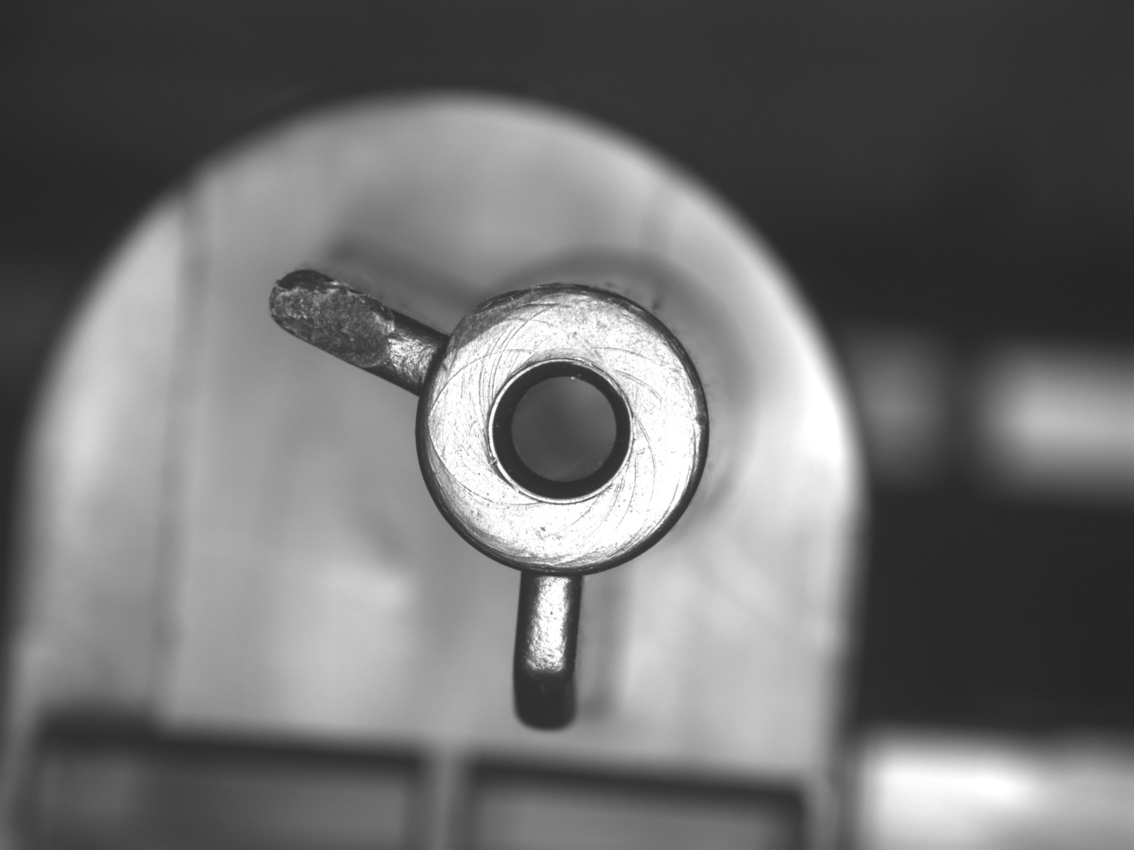
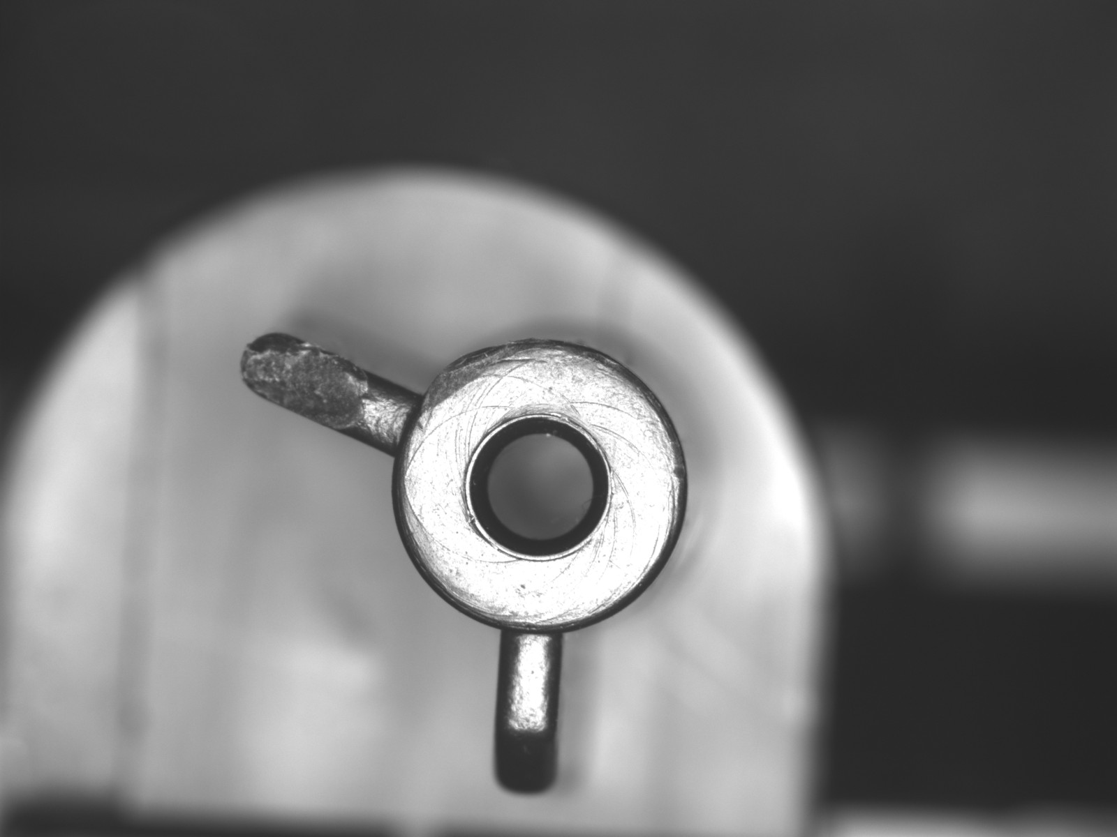
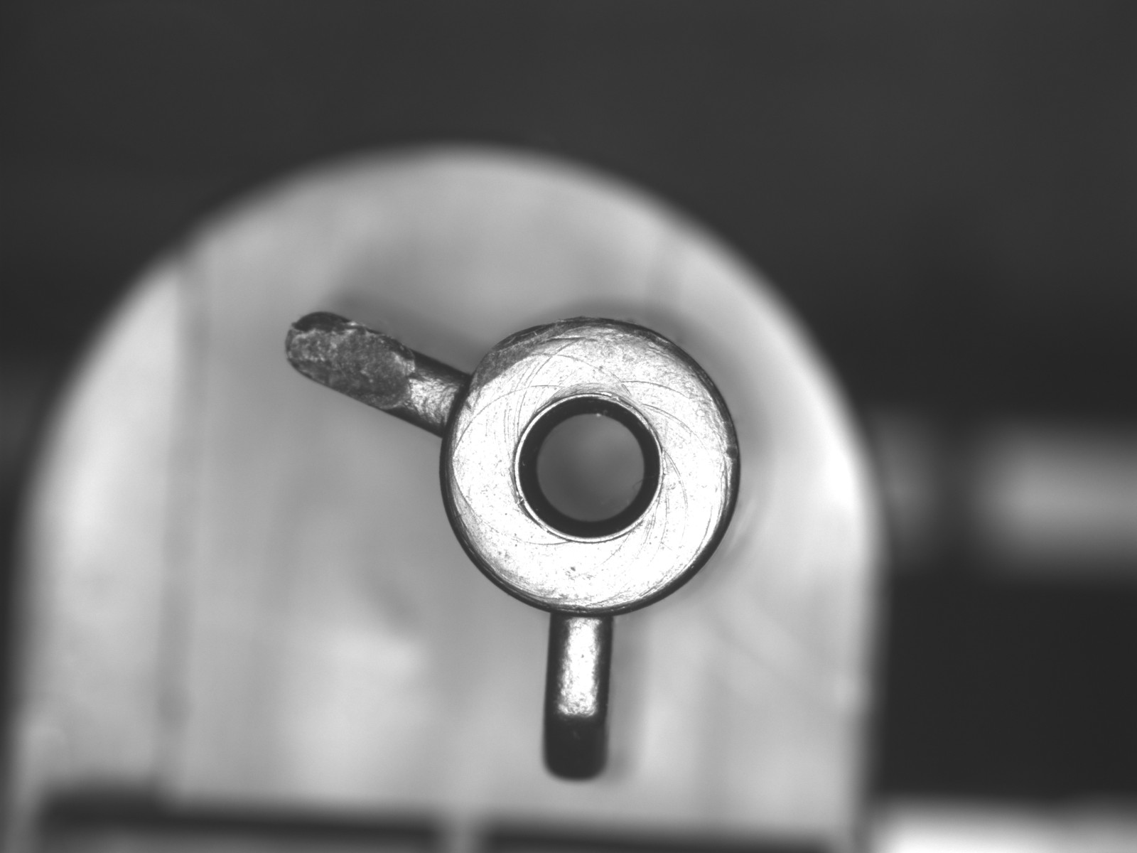
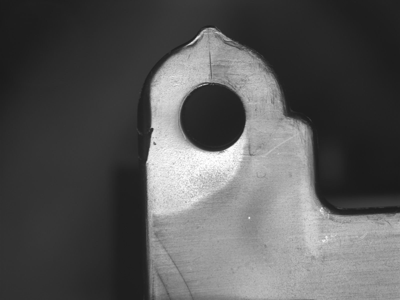
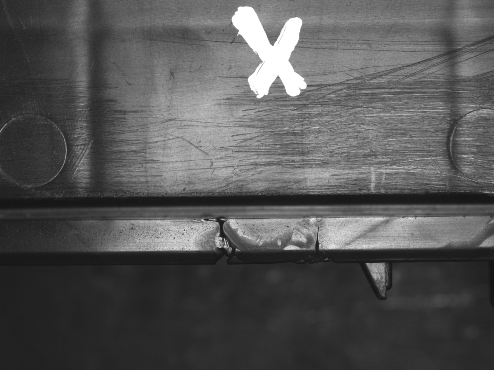
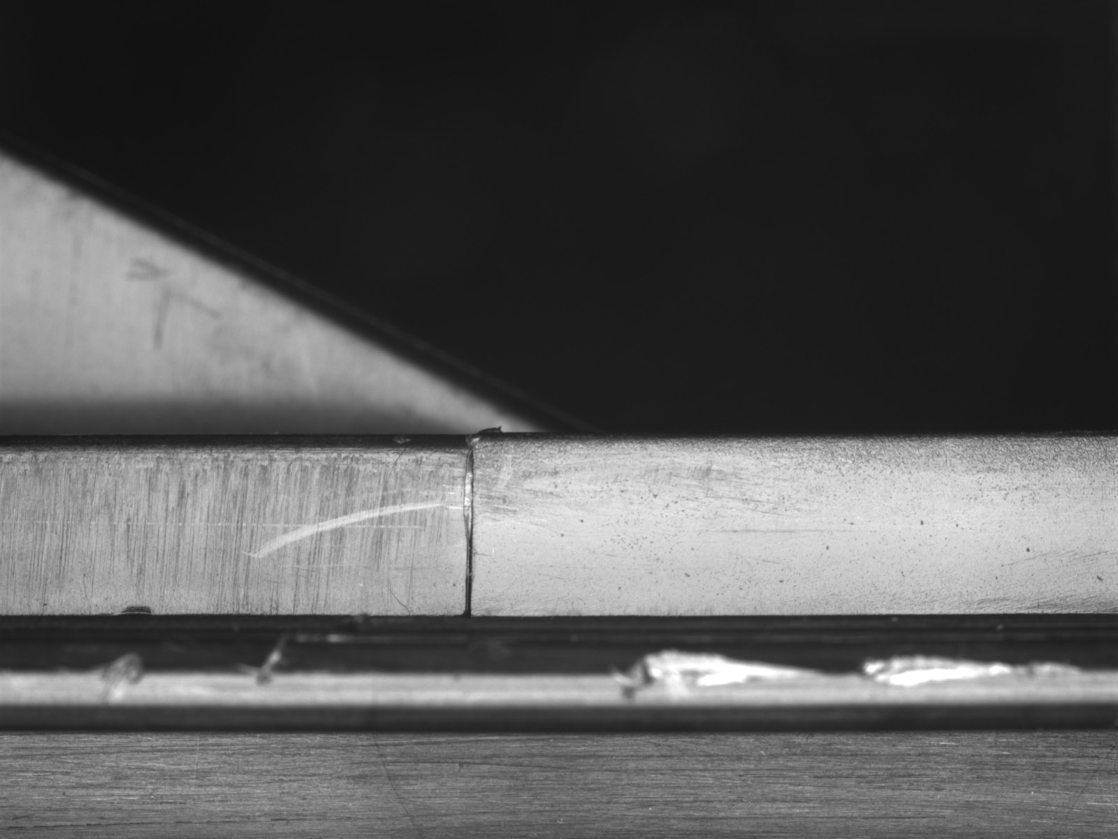
The above are real samples under coaxial light, shown to illustrate the imaging difficulty of local black-part structures; the formal solution switches feasible defects to backlight/dark-field imaging for higher contrast.
Defect Overview & Feasibility
There are 6 target defects: 3 are feasible (defects 1 / 3 / 4) and 3 are high-difficulty and excluded from the current solution (defects 2 / 5 / 6).
| Defect | Nature | Feasibility | Key method | Notes |
|---|---|---|---|---|
| D1 Hook-tip loss / fracture | Missing edge contour | ★★★ Very high | Backlight silhouette | Missing hook tip is obvious; length measurable |
| D3 Bracket loss / deformation | Bottom edge of L-shaped holed bracket | ★★★ High | Backlight silhouette + dark field | Switch to dark field + black background when occluded |
| D4 Snap deformation / whitening | Top protruding snap | ★★ Med-high | Side backlight silhouette + shroud | Requires fixed fixture, isolate shop-floor stray light |
| D5·6 Edge burr height over-tolerance | Burr height vs. datum plane | ✕ Not feasible | — | 2D projection can't reliably convert to true burr height |
| D2 Boss-hole inner arc white edge | White region on inner arc of hole | ✕ Not feasible | — | Tiny white edge easily confused with in-hole highlight; no stable feature |
Note: sizes / working distances are estimated from drawings (hook-tip defects ≈ 0.5 mm, snap deformation ≈ 1 mm); models will be locked once real dimensions are confirmed.
Three Lighting Principles
Lighting is chosen by the physical nature of each defect, with one shared goal: project the defect into a high-contrast feature while avoiding black-part reflection.
Defect 1 · Hook-tip Loss / Fracture
Imaging principle: the hook tip faces the camera with a backlight panel behind; the hook tip becomes a black silhouette, so any loss is obvious and its length can be measured.
Defect 3 · Bracket Loss / Deformation
Imaging principle: the L-shaped holed bracket protrudes on the bottom edge; backlight reveals the silhouette (hole/hook/edge integrity). When the rear is occluded by the body, switch to low-angle dark field + black background.
Defect 4 · Snap Deformation / Whitening
Imaging principle: the camera views the snap horizontally with a backlight behind it; a normal snap has a regular contour, while deformation/whitening makes the silhouette shape abnormal. When deformation only faces the camera, add one grazing light as a backup.
High-difficulty · Excluded from Current Solution
✕ Defect 5·6 · Edge Burr Height Over-tolerance
Actual decision target: measure the true height of the edge burr relative to the datum plane and judge whether it exceeds a specified distance — not merely whether a burr exists.
- Core limitation: image length is a 2D projection and cannot equal the vertical height of the burr.
- An ordinary monocular 2D camera cannot obtain true height information; grazing light only helps reveal burrs, it cannot reliably measure height.
- Conclusion: if height measurement is mandatory, laser triangulation, confocal displacement or a 3D profilometer must be separately validated — outside the scope of this 2D vision solution.
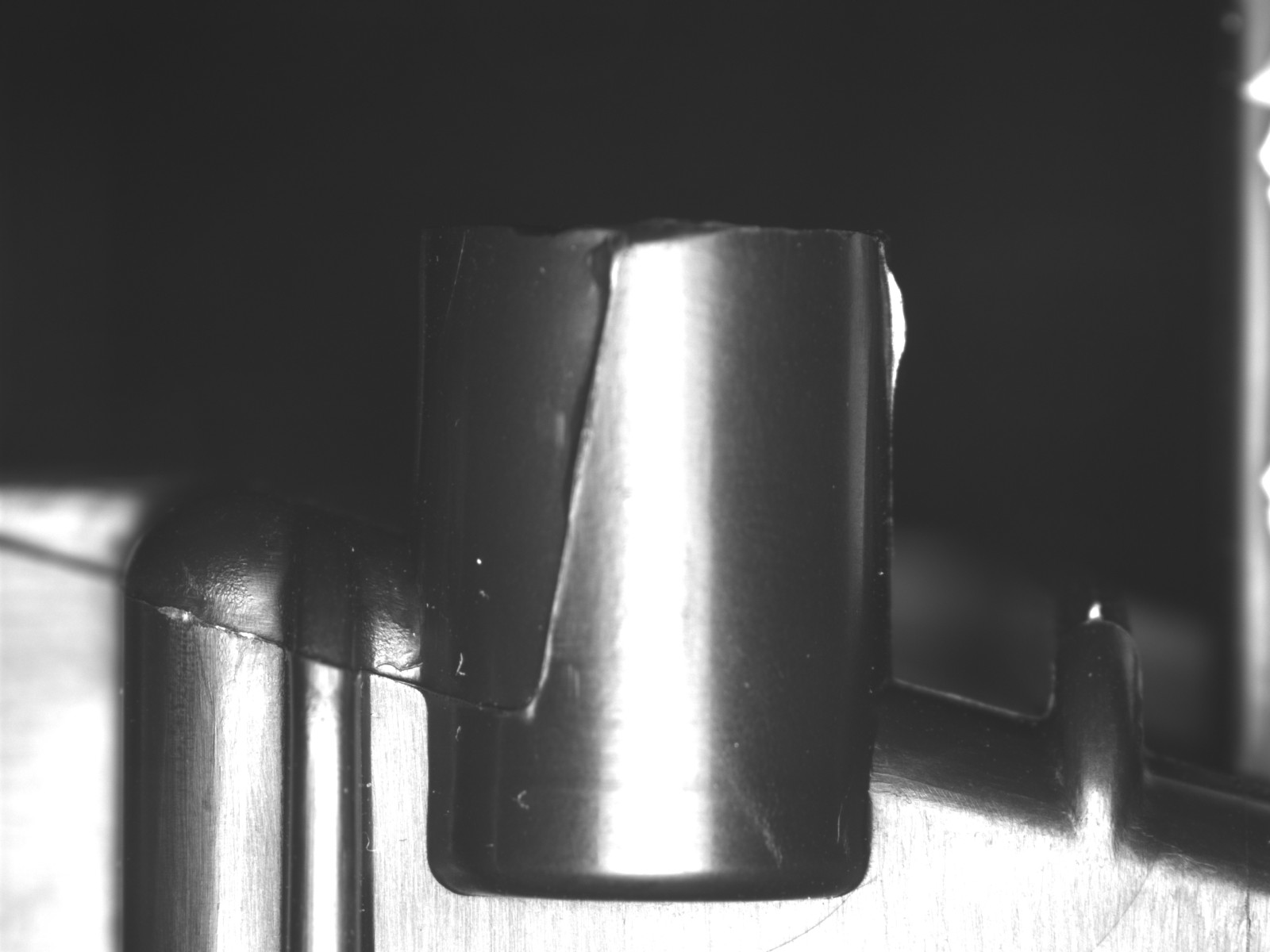
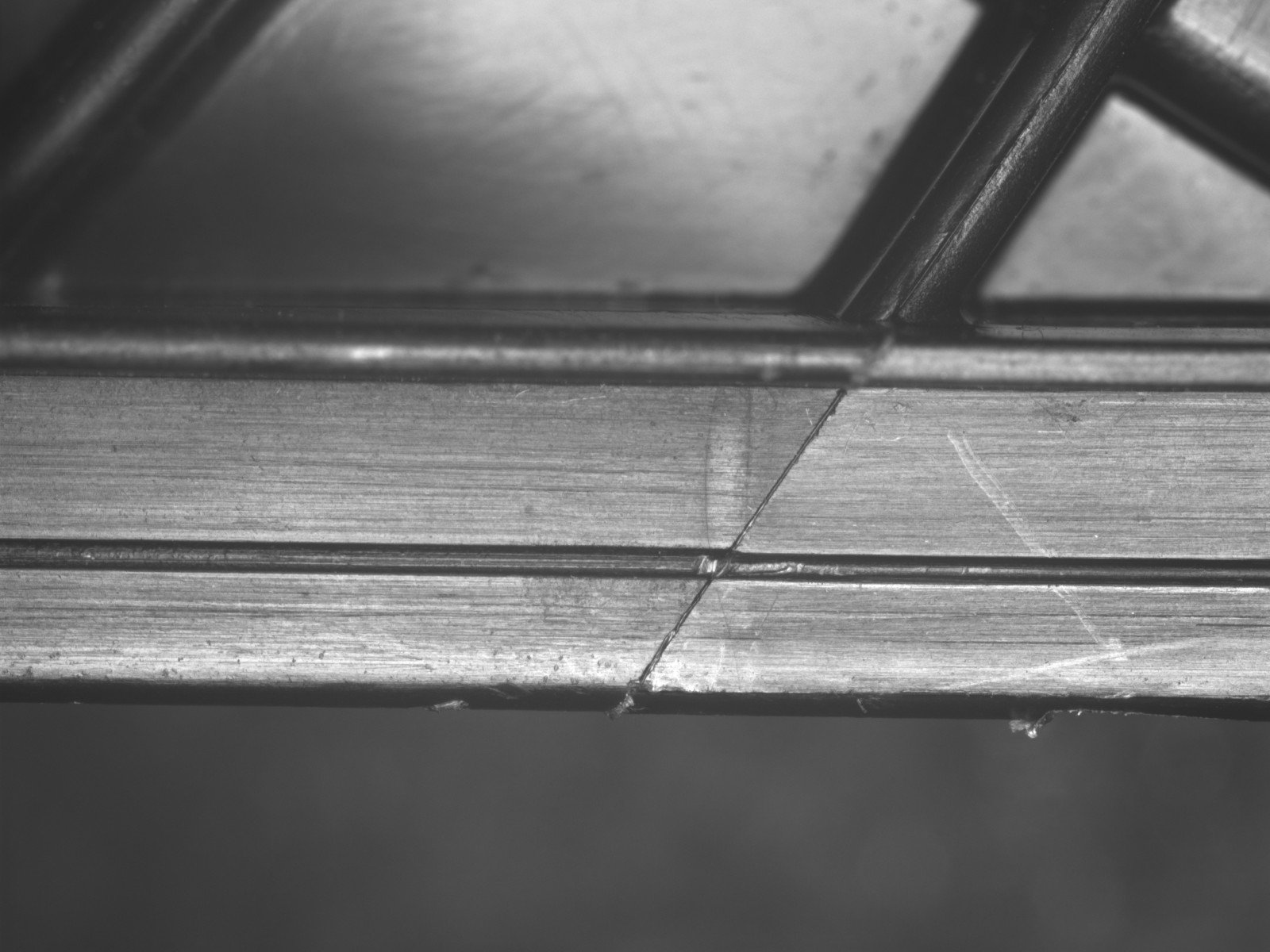
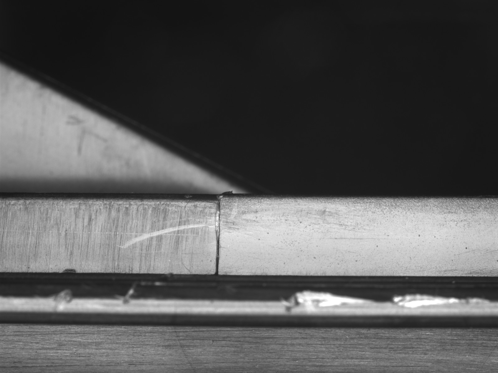
✕ Defect 2 · Boss-hole Inner-arc White Edge
Assessment: high-difficulty, cannot be detected stably. The target is a white edge on the inner arc of the boss hole — unrelated to burrs or height measurement.
- The white edge is small and located inside the hole, easily confused with specular highlights on the black plastic surface.
- Its visible width and brightness change markedly with light angle, camera viewpoint and part pose, lacking a stable, repeatable feature.
- The in-hole space is narrow and occluded, making it hard to control incident and reflected light simultaneously, so both false-reject and false-accept risks are high.
For a dedicated re-assessment: sufficient OK/NG physical samples must be provided with a clear physical defect and decision boundary; a high-repeatability fixture is used to specifically test coaxial, polarized and multi-angle split-light imaging. Only after repeated trials prove the OK/NG features are stable and separable can it be reconsidered — feasibility is not promised at present.
Hardware Baseline & Prerequisites
A common hardware baseline across the three stations — only the field of view and backlight size differ — which simplifies stocking and maintenance.
| # | Equipment | Recommended spec | Purpose |
|---|---|---|---|
| 1 | Industrial mono camera | 2/3" 5 MP (2448×2048, 3.45 µm) | Best SNR for black parts; e.g. Hikrobot MV-CU050 / Basler acA2440 |
| 2 | Industrial lens | 25 mm prime (0.14× telecentric optional for D1) | Common across three stations, easy to stock & maintain |
| 3 | LED backlight panel | Red 660 nm, sized to the FOV | Silhouette imaging for defects 1 / 3 / 4 |
| 4 | Bar grazing dark-field light | Low angle 10°–30°, red/blue | Fallback for D3; surface-deformation aid for D4 |
| 5 | Shroud + locating fixture | Repeat positioning ≤ ±0.5 mm | Isolate ambient light, ensure imaging repeatability (mandatory for D4) |
| 6 | Light controller | Constant current / strobe-synced to camera | Avoid brightness drift; multi-light burst capture |
Prerequisites for accurate recognition (results not guaranteed otherwise)
Items to confirm (once confirmed, models and BOM can be locked)
- Actual sizes of D1 hook tip / D3 bracket / D4 snap → lock camera pixels/lens focal length/backlight size.
- The tolerance for "how small counts as NG" for each defect → set detection thresholds.
- Whether fixtures/shading/multi-light can be installed on site → confirm retrofit space (affects feasibility of D4, D2).
- Cycle-time requirement (inspection time per part) → confirm the camera/light/split-light burst plan.
Conclusion: do the feasible ones solidly, state the infeasible ones clearly
Defects 1 / 3 / 4 image stably with backlight silhouette + dark field and can be deployed on independent stations; defects 2 / 5 / 6 are limited by 2D imaging principles and are explicitly excluded from the current solution to avoid over-promising.