
What the five stations are
- Station 1Line 6F_6B, process 18, manuals into the cartonProcess monitoring
- Station 2Line 6F_6B, process 18, manuals into the cartonProcess monitoring
- Station 3Line 6F_3B, processes 18 and 19, LCD PET align and pressProcess monitoring
- Station 4Line 6F_3B, process 21, LCD bracket and conductive foamAssembly inspection
- Station 5Line 6F_3B, process 22, scan and board assembly into the housingProcess monitoring
Stations 1 and 2: manuals into the carton
One white manual and two yellow manuals go into the carton. A missing sheet or a wrong sequence is usually invisible once the lid is closed. Stations 1 and 2 are two parallel cells of the same process, with the same rule, each running its own state machine.
- EventsWhite manual into the carton; yellow manual into the carton (count to 2).
- StatesWait for white → wait for first yellow → wait for second yellow → cycle complete.
- HoldsYellow before white does not count; one yellow only does not close; a skipped yellow is not backfilled.
The camera looks down at the carton mouth. This station only has to tell white from yellow, not measure to sub-millimeter, so the mount just has to render both manuals as full color blocks. The clip below is packing on the line.
Station 3: LCD PET align and press
Processes 18 and 19 are LCD PET align and press. The shop SOP requires three steps in order: align the round hole, press once with a finger, then press again. A film that sits off the hole, a single press, or the last two steps swapped is hard to catch from appearance after the cover is on. This station is process monitoring: whether the instruction was finished, not whether the finished unit lights up.
- EventsHole alignment done; first press; second press.
- StatesWait for align → wait for first press → wait for second press → cycle complete.
- HoldsA press before alignment does not count; one press only does not close; a skipped press is not backfilled.
The camera looks down at the film area so the hole and the press location share one frame. PET reflects, so this station runs without close fill light—otherwise the film washes out and the hole edge blurs. Pixel scale is set from the hole: hole and film window have to label as separate regions, with the finger press in the same field. The clip below is the cell.
Station 4: LCD bracket and conductive foam
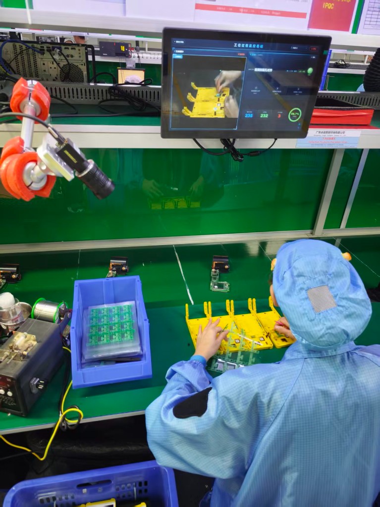
Process 21 installs the zebra-strip bracket and the conductive foam. This station does not run a step grid. It is assembly inspection: whether both parts are in place. The bracket is easier to see; the foam is small and close in color to the bench. A missing piece is often invisible from the housing after the unit leaves the cell, so one missing part should stop the cycle.
- EventsBracket present; conductive foam present.
- CallBoth true to pass. Order is not scored; the state machine does not step.
- HoldsBracket without foam, or foam without bracket, fails the cycle.
The conductive foam is the smallest target across the five stations, and mount height was set from it: the foam has to label as one region, and the bracket then sits in the same frame. The clip below is this station.
Station 5: scan and board assembly into the housing
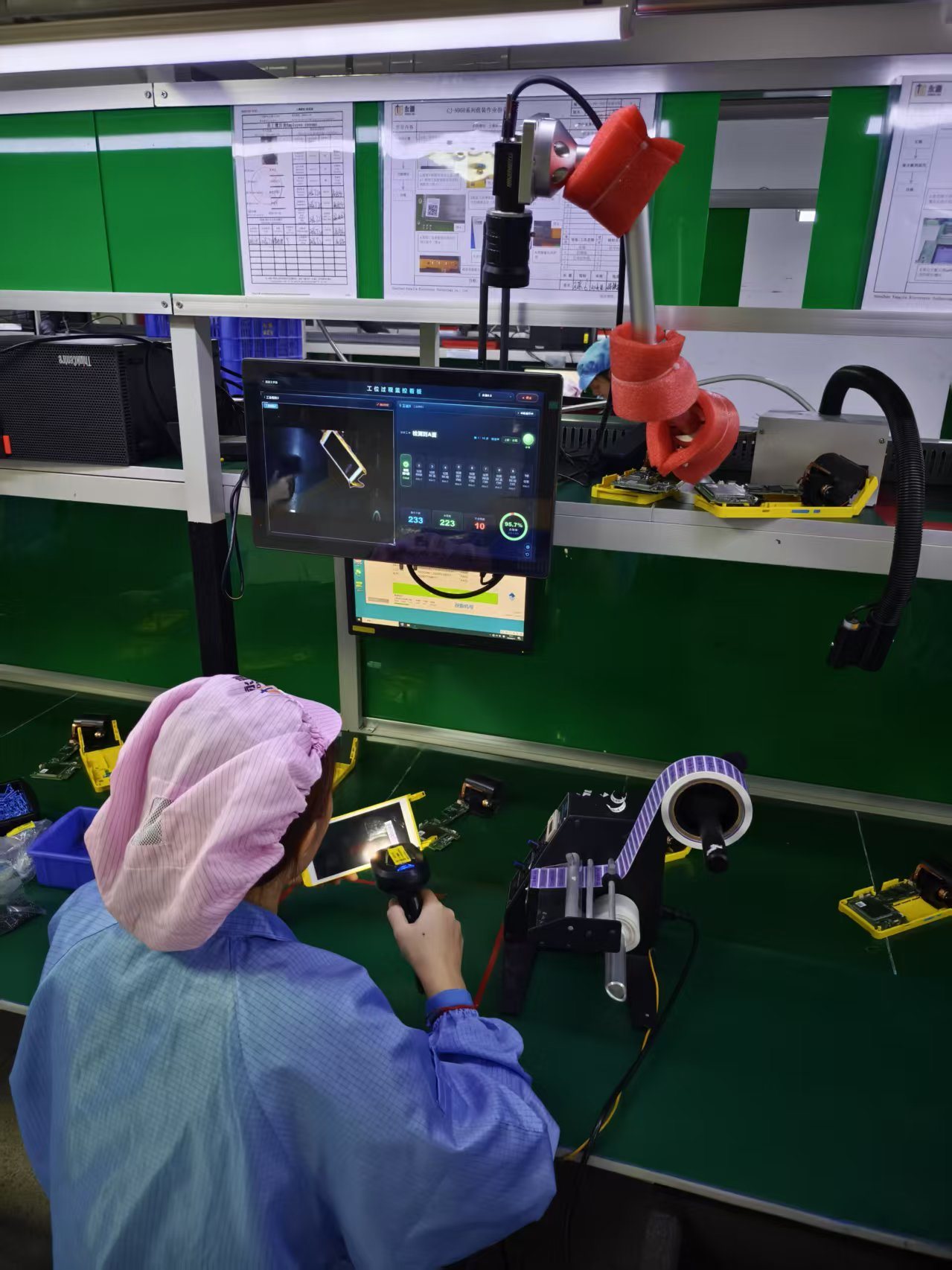
Process 22 requires housing faces A / B / C / D to be in position, with one scan per face, ten steps in all. If only three faces are scanned, it is hard to catch later from appearance. Operators still work as before; the camera grabs frames and checks whether the instruction was finished.
- EventsHousing A / B / C / D in position; scanner completes one scan on the matching face.
- StatesAdvance through the ten instructed steps; the step cells on the board follow.
- HoldsA scan before the face is in place does not count; a skipped face is not backfilled; a partial scan cycle does not close.
The camera looks at the work in front of the operator, with housing and scanner in one frame. Pixel scale is set from the scanner head and the housing edge: both have to label separately, or there is no telling which face a given scan belongs to. The clip below is the scan cell.
What gets deployed on the line
The only hardware that has to go on the line is an industrial camera and an MES station board. The cell does not need its own industrial PC, so rollout stays light and the five stations can go up quickly. Five video feeds run over Ethernet into one unit in a cabinet beside the line. Labeling, transfer, Tensor Stream, and runtime all live in that same stack—adding a station means adding one camera and one screen, not rolling another machine onto the floor.
All five stations share one imaging setup rather than a separate spec per station:
| Camera | Hikrobot MV-CS050-10GC, 2/3″ color, Sony IMX264, global shutter |
|---|---|
| Resolution / pixel | 2448 × 2048 (5.01 MP), 3.45 µm × 3.45 µm, sensor 8.45 mm × 7.07 mm |
| Lens | MT1236-10MP, 2/3″, 12–36 mm manual varifocal, F2.8, C-mount |
| Frame rate / link | 24.2 fps at full resolution, GigE, PoE |
| Light | The illumination already on the line. No bar or ring light added, no close fill on reflective surfaces |
| Mount | Universal mount looking down at the work, one camera per feed |
The varifocal lens is there so one hardware spec covers five cells whose frames look nothing alike. Working from the sensor size and focal length, field of view and pixel scale come out like this:
| Focal length | Working distance | Field of view (W × H) | Pixel scale |
|---|---|---|---|
| 12 mm, wide end | 400 mm | 282 × 236 mm | 0.115 mm/px |
| 12 mm | 600 mm | 422 × 353 mm | 0.173 mm/px |
| 12 mm | 800 mm | 563 × 471 mm | 0.230 mm/px |
| 36 mm, tele end | 600 mm | 141 × 118 mm | 0.058 mm/px |
| 36 mm | 800 mm | 188 × 157 mm | 0.077 mm/px |
That table is what decides how the mounts are placed. With pixel scale in the 0.06–0.23 mm/px band, 30 pixels in the frame covers 1.8 to 6.9 mm, so millimeter-scale parts like the foam and the PET hole still label as their own regions. No swapping in a dedicated fixed-focus lens for them, and no dropping the camera down over the operator's head. The tele end focuses no closer than about 0.5 m, so a mount below that distance is limited to the wide end—which sets the floor on mount height at several of the cells.
Capture does not run at full frame rate. One 2448 × 2048 Bayer 8 frame is about 5 MB, so 24.2 fps is 970 Mbps and all but fills a gigabit link. Assembly actions play out over seconds; SOP adjudication does not need twenty-odd frames per second. Grabbing on the cell's cycle is enough, and the bandwidth saved goes to running five feeds at once.
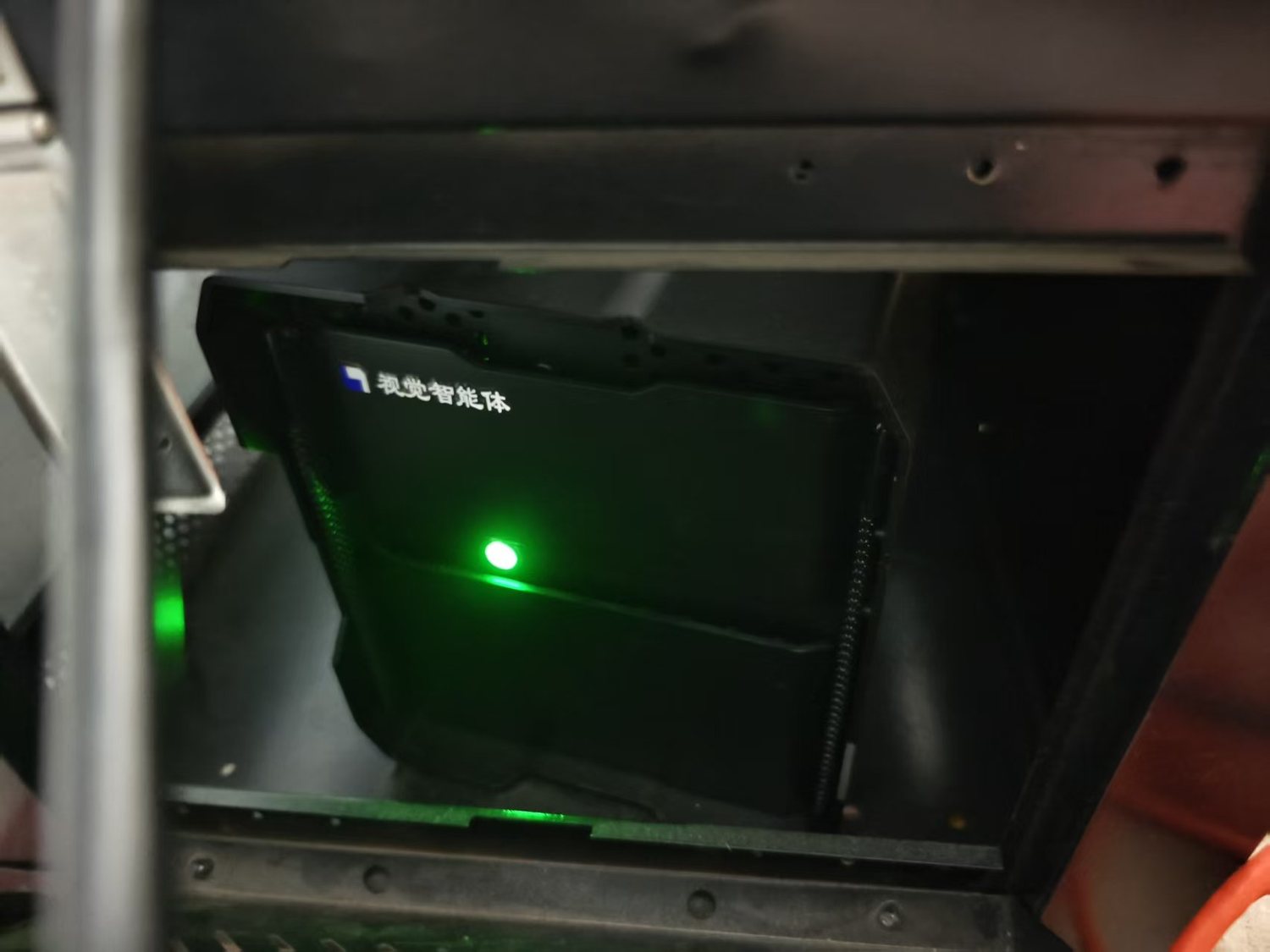
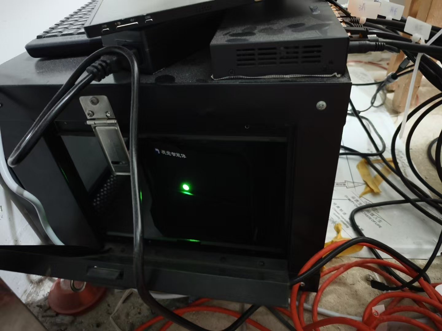
The vision agent is deployed next to the line. Camera management, sample labeling, transfer training, Tensor Stream setup, runtime monitoring, and result output all run in one piece of software on that unit, so the field engineer is not bouncing between tools.
How far few-shot vision models actually go
The five stations look at different targets, so labels are split by station rather than dumped into one pile of shop-floor stills. A conventional small model usually means collecting tens of thousands of images and a training cycle measured in months. A large vision model with few-shot transfer only needs on the order of tens to a hundred labeled images on site. The four classes below map to stations 1 / 2, 3, 4, and 5—about 61, 89, 36, and 98 images. That is the scale. The line went live in seven days.
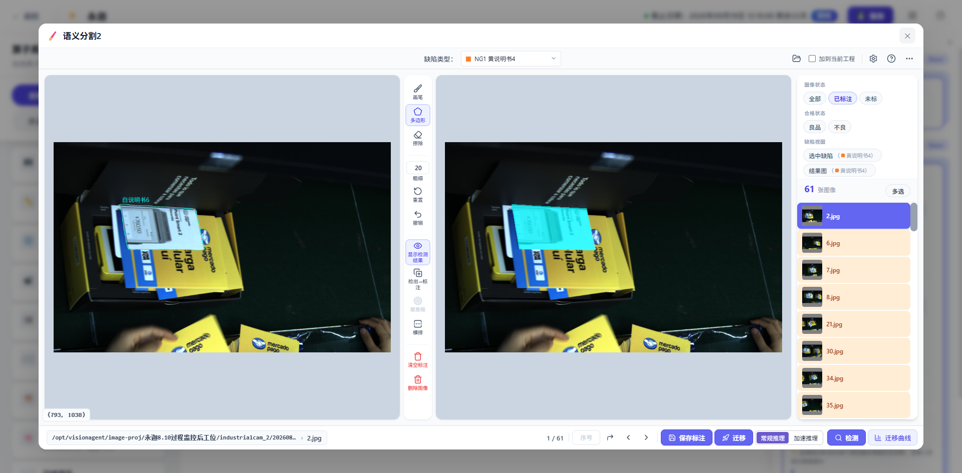
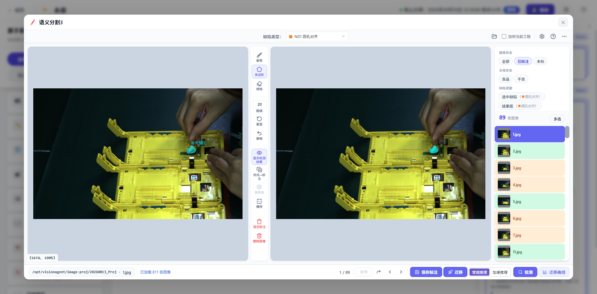
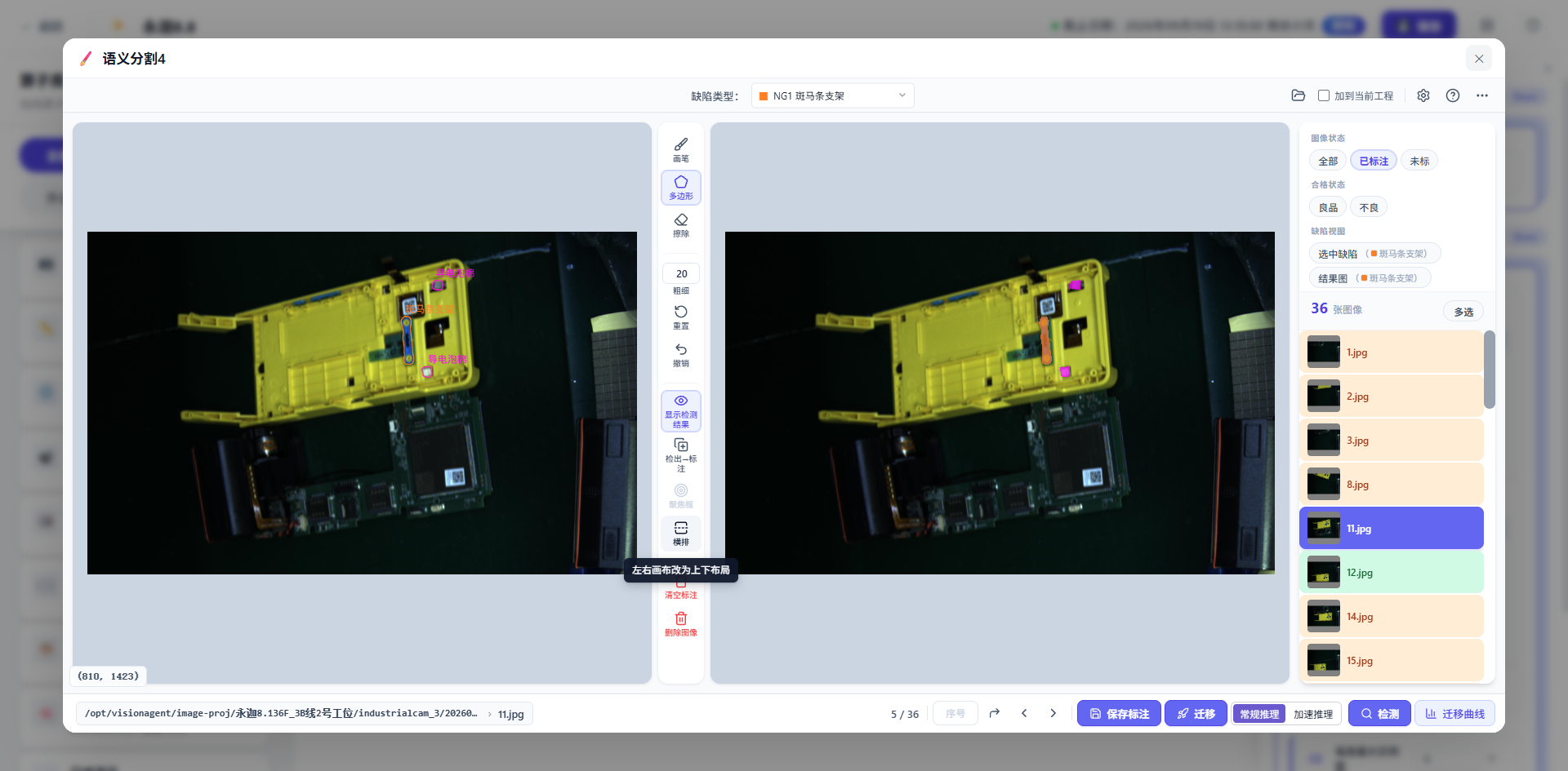

How the five chains attach to the work instruction
The five stations share one canvas. They are not five separate projects. Each chain does the same job: take that camera’s frames, segment the targets that station has to see, then turn those targets into events. Process-monitoring stations feed events into a state machine that follows the instruction. The assembly-inspection station stops at present / absent. Changing a station means changing the targets and the call on that chain, not rebuilding a stack.
Debugging walks down that station’s camera node: whether segmentation still finds the target, whether events fire under that station’s own conditions, then where the state machine stopped. The views differ; the check is the same.

What the board shows once it runs
The verdict does not go into a back-office report. It lands on the station board: the live feed on the left, and cycles, pass, fail, and pass rate on the right. The two station photos above caught the readings in operation—the scan cell at 233 cycles, 223 pass, 10 fail; the assembly cell at 235 cycles, 232 pass, 3 fail. That is 95.7% and 98.7%.
A fail on the board means the cycle did not close: ten steps unfinished at the scan cell, one of the two parts missing at the assembly cell. The call lands at the cell, so the operator looks up and sees whether this cycle passed instead of waiting for a sampling check downstream. Both sets of numbers only reflect the run at the moment the photo was taken; they are not a long-term statistic.
Landing assembly inspection and process monitoring together, quickly, is not the hard part. Quality is caught in the process.