In brief
- What has to be judged is not part appearance but whether the application happened. Once applied, the cloth matches the back panel in colour and shape, so end-of-line inspection cannot tell a missing one from a present one. It has to be caught at the moment it goes on.
- Five classes — applying the label, plus applying a cloth at each of the four positions — were labelled from 1 to 10 sample images each. A rejection has to name which cloth is missing, so the four positions are four separate classes.
- The whole chain sits on one canvas: segmentation recognises, event detection confirms position and stability, the state machine accumulates to a verdict. The three layers are edited independently.
- Every acceptance rule lives on the state diagram, not in the model, so it can be tailored to each customer's floor with no retraining and no code.
What the station looks like
A manual station on an assembly line. The workpiece has a metal back panel. When it arrives, the operator first applies a label at a designated spot, then applies four anti-static cloths to four positions on the panel. The unit moves on and the next one arrives.
The core tension: a missing cloth is invisible on the spot
The anti-static cloths bond to the metal back panel and drain the static charge that builds up during assembly, handling and packing. Leave one off and the charge has one path it cannot take; what suffers is the sensitive electronics behind that panel.
The awkward part is that this failure does not show up on the spot. The unit carries on down the line, powers up normally and passes functional test. The problem tends to surface at burn-in, or in the customer's hands, as image artefacts, blank screens or random lock-ups. By then tracing means pulling a whole batch and repair means stripping a finished unit — costs that are nowhere near the price of one cloth at this station.
So the nature of this operation is: high consequence of failure, and no error-proofing whatsoever at the station itself. The cloths go on by hand — no torque, no count, no presence sensor. The positions are soon covered by downstream parts and the top cover, so static end-of-line inspection cannot see them. Operator self-check is no check at all, and sampling does not cover every unit.
The only remaining way to confirm it is to watch the cloth go on. That is the direct reason for adding vision here — not to replace final inspection, but because final inspection cannot see this item at all.
The acceptance rule therefore narrows to two lines: a complete set of four is OK; the unit leaving with one still missing is NG, and the record has to say which one. The sections below break those two lines down into the actual configuration in the platform.
What it produces
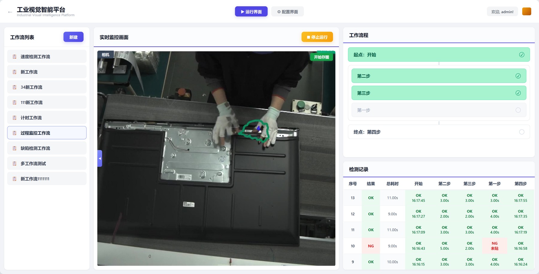
The result first, then how it was built. On the running screen, the top right shows which cloths the current unit has, the bottom right the per-unit log.
Tensor flow: one pipeline from video to record
Everything is configured on a single canvas. Video enters on the left and exits on the right as records and saved images; each block in between is an operator and each link is a data path. Once this diagram is set, the station runs — no scripts, no build step, saved changes take effect immediately.
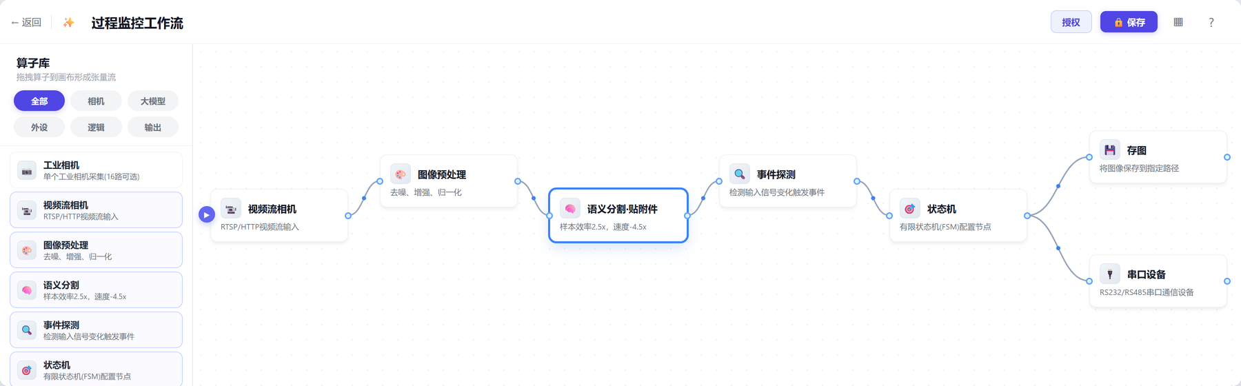
| Operator | What it does here | Key setting |
|---|---|---|
| Video camera | Takes the RTSP stream from the overhead camera | 1080p / 25 fps |
| Preprocessing | Suppresses conveyor glare and overhead-light flicker | Denoise, normalise |
| Segmentation · applied items | Outlines the label and the four cloth applications frame by frame | 5 classes |
| Event detection | Turns segmentation into events such as "cloth N applied" | 7 events |
| State machine | Owns the start, the running count, the verdict and the record | 4 states / 3 actions |
| Image saving | Stores the frame automatically on NG | NG only |
| Serial device | Sends OK/NG to the station light and the line system | RS485 |
The whole flow runs on one edge GPU beside the line. Video never leaves the shop floor and nothing depends on plant network stability — if the network drops, the station keeps judging and keeps recording, and back-fills when it returns.
Segmentation: showing the system what an applied cloth looks like
This layer solves "can it recognise". You outline the application region on a handful of real frames in the labelling tool and give it a class index — no rules, no thresholds, outline it and train.
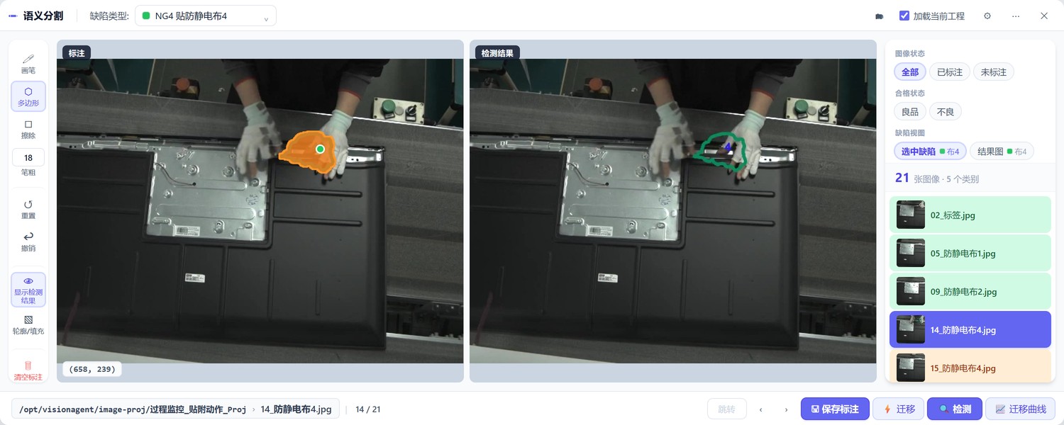
What gets outlined is the shape of the application as a whole, not the cloth. The hand, the cloth being pressed down and the patch of panel underneath all go inside the outline. Outline only the cloth and it looks much the same held in the hand as pressed on the panel; outline only the hand and the four positions become indistinguishable.
The four cloths are four classes rather than one "cloth" class with four regions, for a very practical reason: an NG has to name which one is missing. An operator taking the record back to fix it needs to know which position. The panel texture and surrounding parts differ at all four positions, so the model separates them more easily than one might expect. With the label, that makes five classes.
Each class was labelled from a handful of images. What few-shot capability means here in practice is that a new application position goes from field images to working in 1 to 10 samples and a few minutes of configuration. That is what makes a model change possible without calling a training engineer back to site — a process engineer outlines a few frames, hits "detect" to see how it looks, and adds two more if it is not there yet.
The commissioning check is simple: replay footage that was not part of training and watch whether the five contours appear when they should and disappear when they should. Jitter and the odd dropped frame do not matter; the next layer filters them out.
Event detection: a hand carrying a cloth past does not count
Segmentation gives a per-frame "there is an application shape here". Turning that into "cloth 4 is on" needs two more conditions: right position, and it has to settle. That is what this layer does, configured in the event orchestrator without touching the model.
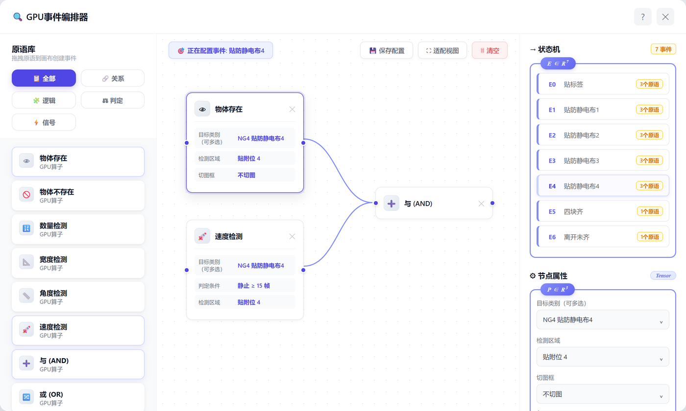
The stability condition came out of commissioning. With object presence alone, an operator reaching into the material box or passing a hand over the panel would trigger it — the system believed a cloth was on while it was still in the hand. That false positive is the dangerous one: it records a unit with a missing cloth as OK, letting through exactly what the project exists to catch. Requiring the target to hold still for a run of consecutive frames removed it.
The detection region matters just as much. The four cloths look identical, so only the region confirms which position was served; and operators from the neighbouring station occasionally walk into frame, whose actions would otherwise be counted against this unit. The region is a box drawn on this page — change the line layout or the model, change the box.
| Event | Trigger | Purpose |
|---|---|---|
| E0 Apply label | Label class + region + stability met | Start the unit |
| E1 Apply cloth 1 | Cloth 1 class + position 1 + stability met | Count one |
| E2 Apply cloth 2 | Same, different class and region | Same |
| E3 Apply cloth 3 | Same | Same |
| E4 Apply cloth 4 | Same | Same |
| E5 Set complete | Count check: cloths applied = 4 | Unit complete |
| E6 Left incomplete | Object absence: the workpiece leaves with fewer than 4 | NG: save image and flag which is missing |
E6 uses the "object absence" primitive — the workpiece leaving the detection region is what says this unit is over and needs settling. Using the workpiece itself as the settling signal is more reliable than any external trigger, and needs no extra wiring.
State machine: start, accumulate, settle
By this layer the system already knows which cloth went on. What remains is gathering those events into a verdict for the unit. That is decided entirely by the state diagram, independently of the model.
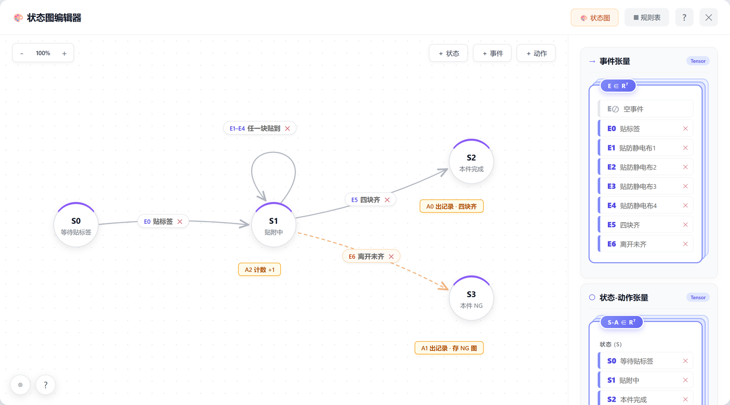
The self-loop is the core of this diagram. It accumulates the four cloths as a set: each application leaves the state unchanged and only increments the count, and the real decision is deferred to the moment the set is checked. On the whole diagram NG has exactly one cause — the workpiece left and the set was not full — and which cloth is missing is obvious from the classes already counted.
Writing it this way has another benefit: adding or removing a position does not change the structure. One more position means one more class and one more event wired into the same self-loop, plus a change to the count on E5. The shape of the diagram stays the same.
| State | Waiting for | Exit |
|---|---|---|
| S0 Await label | The start action of this unit | E0 → S1 |
| S1 Applying | Four anti-static cloths | E1–E4 self-loop (A2 count +1) / E5 set complete → S2 / E6 left incomplete → S3 |
| S2 Unit complete | — | Emit record (A0), reset to S0 |
| S3 Unit NG | — | Emit record and save image (A1), reset to S0 |
Rules tailored to the site, without rebuilding the system
The same four cloths at another plant, on another line, may come with completely different requirements — one more position, only two positions mandatory, operators allowed to fix it on the spot, or an alert rather than a rejection. Differences like these should not have to be absorbed by developing another program.
This is where the division of labour across the three layers pays off: the model only recognises, region and stability decide accuracy, and everything about "what counts as acceptable" is concentrated on one canvas — the state diagram. Tailoring therefore usually involves no training and no code, just a few edits on that diagram:
| What the site asks for | The change | Blast radius |
|---|---|---|
| One more application position | Add a class and an event into the S1 self-loop, change the count on E5 | One class, one event, same diagram |
| Only two positions mandatory | Change the count condition and target classes on E5 | One event parameter |
| Let the operator fix it on the spot | Add a link from S3 back to S1 | One link added |
| Alert only, no rejection | Swap S3's action from "record and save image" to "notify only" | One action |
| A different settling signal | Swap E6's primitive from object absence to a line index signal | One primitive |
| Mixed models, different positions | One workflow per model, switched automatically by label content | Copy the workflow, edit regions |
Tailoring is not limited to acceptance rules. Which fields the record carries, whether NG images are stored and for how long, whether the result drives a station light or writes into a particular field of the line system — all of it is configuration. That is how this station's final shape was agreed: the floor wanted only a station light and the per-unit log, MES takes OK/NG and the missing position, nothing else is pushed.
The price of making rules configurable is more settings than a hard-coded program would have. What it buys is a system that moves with the process — this station's acceptance rule was adjusted twice during the project at the site's request, and both times the change was made and production resumed within the same shift, with no line stoppage and no retraining.
What to prepare before going live
From an IT and automation point of view the list is short, but every item has to be settled up front.
| Item | Requirement | Note |
|---|---|---|
| Camera | 1080p or better, 25 fps, RTSP | The mount must look down on the whole panel with none of the four positions blocked by the operator's body |
| Lighting | Stable illuminance, no direct glare | Glare off the metal back panel is the most common source of interference here |
| Compute | One edge GPU beside the line | One unit serves several stations, sized by camera count |
| Network | Camera and inference host on the same gigabit segment | Inference is local and does not depend on the plant backbone |
| Output | RS485 or Ethernet | To a station light or andon board, or per-unit records into the line system |
| Retention | NG images stored locally, rolling by day | NG only, so storage pressure is minimal |
Allow a week for commissioning. Day one for the mount and getting the video stream up; days two and three for labelling the five classes and tuning segmentation against replays; days four and five for drawing the position regions and setting the stability condition; the last two running alongside manual records to confirm there are no false calls.
Lessons
1. Separating "can it recognise" from "does it judge correctly" is what lets a project like this converge. The model only recognises the application shape; position, stability and the settling rule all sit outside it. Most of the commissioning effort goes into those outer layers, and each change there takes minutes rather than a training run.
2. False triggers are far more dangerous than misses. Reaching for material or passing a hand over the panel can make the system believe a cloth is on, recording a unit with a missing cloth as OK — exactly what the project exists to catch. The fix is not in the model but a stability condition in the event layer.
3. How you split classes follows from what the rejection has to say. The only reason the four cloths are four classes is that a miss has to name the position. Deciding what the record should look like first, then working back to the class list, is much less work than the other way round.
4. Keeping the acceptance rule on the diagram is why this travels. Adding a position, changing which are mandatory, swapping the settling signal — all rewiring and parameters. When replicating across plants, that is worth far more than another point or two of raw recognition accuracy.
This approach fits manual stations where product, process and line change often and where the defect is invisible on the spot but expensive once it escapes. One edge GPU can serve several stations across several lines, the configuration copies directly between stations, and the rules are then adjusted to each site — which is where it costs less than writing a bespoke inspection program per station.
About the author
PhD in computer vision, working on few-shot segmentation and video action understanding; 12 years on the industrial vision shop floor, with 30+ production lines and 100+ stations delivered.
Currently focused on edge GPU inference optimisation, cross-domain generalisation and closing the loop on field data — so that the same way of configuring a system transfers between plants and processes. These articles record the actual configuration, decision logic and field results of real deployments.